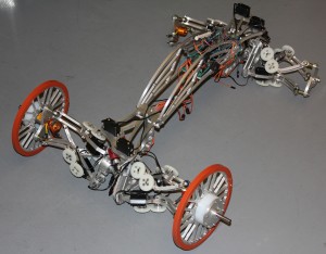
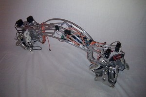
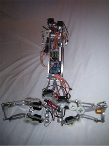
Here are some new images of the vehicle with the two front wheels mounted. It is shown in both the completely extended and retracted positions to show the range of motion. Only the back two wheels are missing since these must be built to accommodate the optical encoders.
Telescoping Suspension Trial
Here’s a quick video of a single telescoping suspension arm. It is being controlled manually with three potentiometers for extension, pivot x, and pivot y. This setup was also used in the calibration procedure with a Johnson magnetic angle finder.
Posted in Uncategorized.
rev="post-31" 1 comment
Workspace
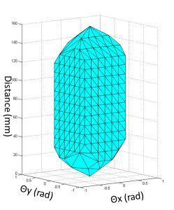
Traditionally, a robot’s workspace is the volume bound by the end effector. In this telescoping suspension arm’s case, I believe that the workspace can be considered as the pivot that can be achieved by the arm at various extensions. Also, it makes a very interesting shape!
Posted in Uncategorized.
rev="post-26" No comments
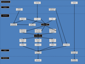
Block Diagram
Here is a very preliminary high level block diagram for one telescoping suspension arm. It gives a good idea of what the vehicle is monitoring and how the linkage geometry interrelates.
Posted in Uncategorized.
rev="post-23" No comments
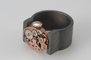
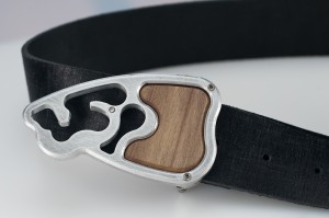
Some Machining
I have a Tormach CNC mill which I use to machine almost all of the parts for my prototypes. It also affords me other interesting opportunities, here are some aesthetic things I’ve machined:
Posted in Uncategorized.
rev="post-16" 1 comment
Full Assembly
This post is to give some perspective of the complete telescoping suspension arm vehicle. A 3dpdf can be zoomed and manipulated.
Posted in Uncategorized.
rev="post-13" 2 comments
Cytron Optical Encoder with Arduino
One of the advantages of a vehicle with variable track width is that it can easily counteract the forces due to centrifugal acceleration. This acceleration can be calculated as the square of the velocity divided by the radius of curvature of the vehicle. The controller will therefore need to monitor the vehicle’s instantaneous velocity since the radius of curvature can be determined geometrically from the arm positions.
There are many ways to measure velocity with a microcontroller, and I have chosen to use an optical encoder to as the rotational direction provided by mechanical quadrature encoders is not necessary. Specifically, I am using a Cytron simple rotary encoder kit, available here. It is simple and relatively cheap, but I was unable to find any sample code to measure velocity with an Arduino. I wrote my own and have posted it below, hopefully it is helpful to someone just learning. It uses interrupts to count the pulses of the encoder and then sends the velocity serially every second. The wheel radius and rate of velocity calculations can be adjusted as desired. It is important to note that the current_time variable has to be volatile so it doesn’t get buried under the stack when other processes are running.
The 5v and ground pins can use the Arduino’s built in supply, and the signal pin is connected to digital pin 2: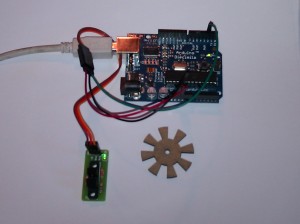 The Code:
int hits = 0;
float wheel_radius = 1;
volatile unsigned int current_time;
long time_interval = 1000; //how often do you want to know velocity (milliseconds)
float velocity; //this is the velocity in length units / time_interval

void setup ()
{
  Serial.begin(9600);
  attachInterrupt(0, count, CHANGE);
  current_time = millis();
}

void loop ()
{
  if ( millis() >= current_time + time_interval)
  {
    velocity = (hits*(wheel_radius * 392.7))/time_interval;//the constant is 2*pi*1000/16
    Serial.println(velocity);
    hits = 0;
    current_time = millis();
  }
}

void count()
{
 hits++;
}
Posted in Uncategorized.
rev="post-10" 2 comments
Telescoping Active Suspension
This is a project that I am working on over the summer. I am building another active suspension vehicle with independent suspension and a novel telescoping arm system. This means that the vehicle can alternate track width on the fly to be more compact or stable as necessary. More information can be found in my paper that I will be presenting at the IEEE/ASME conference on Mechatronics in Montreal July 6-9th, 2010. Â I will be working on this project over the summer under the auspice of Dr. Luis Rodrigues‘ HYCONS lab funded by NSERC and CIADI. This quick video demonstrated the mechanism in the suspension arm:
Posted in Uncategorized.
rev="post-9" No comments
Archives
Since this is my first post, I will upload some of my older projects reverse-chronologically to give this blog some context:
My most recent completed project is a proof of concept of an active suspension solid axle off-road vehicle. An accelerometer on the front axle reads the tilt angle of the axle and this is converted into an angle that is sent to a servo which drives a cam and link system. The controller adds shock preload to the left or right side of the vehicle to keep the central (cab) portion of the vehicle stable while overcoming harsh terrain. This vehicle worked quite well at dampening out low frequency perturbations but would not be appropriate for smaller, more frequent, disturbances. The nature of a solid axle system is also ideal for particularly rough terrain.
I was interested in legged transportation and built a 2DOF/leg hexapod from scratch. It proved to be quite rhobust mechanically, but could use more work refining the leg movements. It was an interesting process, but issues with servos meant that the platform was not suitable for further experimentation.
This is an early experiment with a solid axle off-road vehicle. I wanted to build something slow but capable offroad. A hobby motor was mounted onto a cordless drill gearbox which was connected to locked differentials from a remote controlled car. The vehicle suspension proved to work well off-road but was too soft for flat terrain.
Posted in Uncategorized.
rev="post-1" No comments
